Module 16 — Piston Engine
16.1 — Fundamentals
On this page (5)
Introduction
The piston engine (reciprocating engine) converts the chemical energy in aviation fuel into mechanical energy through a repeated cycle of combustion events inside cylinders. Despite being one of the oldest forms of aircraft powerplant, piston engines remain the dominant choice for light aircraft, trainers, and many general aviation types. Every Part 66 engineer working on these aircraft must have a thorough understanding of piston engine theory.
Operating Principles
The Four-Stroke (Otto) Cycle
The vast majority of aircraft piston engines use the four-stroke Otto cycle. Each cylinder completes four distinct strokes (two complete crankshaft revolutions = 720°) to produce one power event:
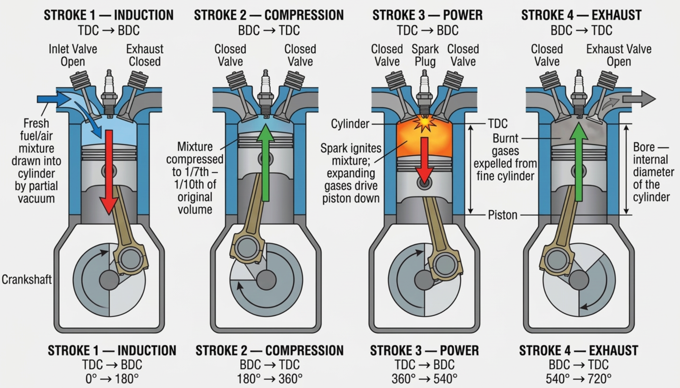
Memory aid — "Suck, Squeeze, Bang, Blow": This classic mnemonic summarises the four strokes: Induction (suck mixture in), Compression (squeeze it), Power (bang — ignition and expansion), Exhaust (blow gases out).
Stroke-by-Stroke Detail
| Stroke | Piston | Inlet Valve | Exhaust Valve | Crankshaft | Action |
|---|---|---|---|---|---|
| 1 — Induction | TDC → BDC | Open | Closed | 0° → 180° | Fresh fuel/air mixture drawn into cylinder by partial vacuum |
| 2 — Compression | BDC → TDC | Closed | Closed | 180° → 360° | Mixture compressed to 1/7th – 1/10th of original volume |
| 3 — Power | TDC → BDC | Closed | Closed | 360° → 540° | Spark ignites mixture; expanding gases drive piston down |
| 4 — Exhaust | BDC → TDC | Closed | Open | 540° → 720° | Burnt gases expelled from cylinder |
Key terms:
- TDC — Top Dead Centre: piston at highest point in cylinder
- BDC — Bottom Dead Centre: piston at lowest point in cylinder
- Stroke — distance between TDC and BDC
- Bore — internal diameter of the cylinder
The Otto Cycle as a Thermodynamic Cycle
The four strokes describe what the hardware does. The Otto cycle is the thermodynamic idealisation of what the gas inside the cylinder does, and it is the form the examination tests. The ideal cycle has four processes, of which only two are strokes in the mechanical sense:
- 1 → 2 Isentropic compression. The trapped charge is compressed with no heat entering or leaving it. Pressure and temperature both rise; the temperature rise comes entirely from the work done on the gas, not from any heat source.
- 2 → 3 Heat addition at constant volume. The charge burns while the piston is assumed to be stationary at TDC, so the volume does not change while the heat is released. Pressure and temperature jump almost vertically on a pressure–volume diagram.
- 3 → 4 Isentropic expansion. The high-pressure gas drives the piston down, doing work on it, again with no heat crossing the boundary.
- 4 → 1 Heat rejection at constant volume. In the idealisation the residual heat is simply dumped at BDC. In the real engine this is the blowdown through the opening exhaust valve followed by the exhaust stroke.
The single defining feature, and the one the examiner is looking for, is that the Otto cycle adds its heat at constant volume. It is often described in one phrase as a constant-volume combustion cycle. Everything else about it — spark ignition, a pre-mixed charge, a modest compression ratio — follows from wanting the whole charge to burn in the very short window while the piston is near the top of its travel.
Air-standard Otto efficiency:
\[ \eta_{ideal} = 1 - \frac{1}{r^{\gamma - 1}} \]
Where \( r \) is the compression ratio and \( \gamma \) is the ratio of specific heats of the working fluid, taken as 1.4 for air.
Note what is not in this expression: fuel, mixture strength, engine speed, cylinder count. In the ideal cycle the thermal efficiency of a spark-ignition engine depends on the compression ratio alone.
Worked example — the ideal ceiling at three compression ratios:
At \( r = 7 \): \[ \eta = 1 - 7^{-0.4} = 1 - 0.459 = 0.541 = 54.1\% \]
At \( r = 8.5 \): \[ \eta = 1 - 8.5^{-0.4} = 1 - 0.425 = 0.575 = 57.5\% \]
At \( r = 10 \): \[ \eta = 1 - 10^{-0.4} = 1 - 0.398 = 0.602 = 60.2\% \]
Raising the compression ratio from 7:1 to 10:1 lifts the ideal ceiling by about six percentage points. That is the whole reason designers push compression ratios upward, and the whole reason they are stopped by detonation before they get very far.
A real spark-ignition aero engine delivers around half of that ideal figure. The shortfall is not one large loss but a stack of unavoidable ones: heat conducted into the cylinder head and barrel while the gas is hottest; combustion that takes tens of crankshaft degrees rather than happening instantly at TDC; the exhaust valve opening before BDC so that some expansion work is thrown away to reduce the pumping effort of the exhaust stroke; the work of drawing the charge past the throttle butterfly and pushing the burnt gas out again; chemical dissociation at peak temperature; incomplete combustion; and, at high power, deliberate mixture enrichment used purely to cool the charge and the exhaust valve. On top of all of that, the practical figure quoted for an engine is normally referred to shaft power, so the friction of the engine itself is inside the gap as well.
Real Valve and Ignition Timing
The stroke table above places every event exactly at TDC or BDC. No engine is built that way. Gas has mass and therefore inertia, valves take time to lift and seat, and the charge takes a measurable time to burn, so every event is moved away from the dead centre a textbook cycle would put it at.
- Inlet valve opens before TDC. The valve is off its seat and flowing by the time the piston starts down, so the cylinder is not trying to draw through a barely-cracked valve during the fastest part of the induction stroke.
- Inlet valve closes after BDC. The incoming charge is moving at speed; its momentum keeps it flowing into the cylinder for a while after the piston has stopped descending and started back up. Holding the valve open captures that extra charge. This is also why the point of inlet closure, not BDC, marks the true start of compression.
- Exhaust valve opens before BDC. Some expansion work is deliberately sacrificed so that most of the cylinder pressure has blown down before the piston starts up. The pumping work saved on the exhaust stroke is worth more than the expansion work given away.
- Exhaust valve closes after TDC. The outgoing gas column has momentum too, and continues to scavenge the cylinder briefly after the piston has reached the top.
Because the inlet opens before TDC and the exhaust closes after it, there is a period around TDC at the end of the exhaust stroke when both valves are open together. This is valve overlap, and it is deliberate. The exhaust gas leaving at speed lowers the pressure at the top of the cylinder and helps pull fresh charge in; the fresh charge sweeping past the exhaust valve carries heat away from the hottest component in the combustion chamber. At the speeds an engine spends most of its life at, overlap is worth having.
The cost appears at the other end of the speed range. At idle the gas velocities are low, so instead of scavenging, overlap allows exhaust gas to be drawn back into the cylinder and inlet tract. The charge is diluted with inert burnt gas, combustion becomes less reliable, and the engine idles roughly and needs a richer mixture to fire at all. That is why a large-overlap engine is lumpy at idle and cleaner once the throttle is opened.
Ignition timing is displaced for the same reason. Burning a cylinder full of mixture is not instantaneous; the flame front takes an appreciable slice of crankshaft rotation to cross the chamber. To have the pressure peak arrive where it can do useful work — a little after TDC, of the order of ten to fifteen degrees, when the crank has enough leverage on the connecting rod — the spark must occur while the piston is still rising. On a fixed-timing magneto installation the spark is typically set somewhere in the region of twenty to twenty-five degrees before TDC, with the exact figure fixed by the engine type certificate data sheet and the engine maintenance manual, never by a rule of thumb.
Getting the timing wrong, in both directions:
- Too far advanced — combustion is largely complete while the piston is still coming up, so the peak pressure is higher and arrives earlier, opposing the piston. Cylinder head temperatures climb, exhaust gas temperature tends to fall because more of the heat is released into the cylinder rather than into the exhaust, and the end-gas is squeezed harder for longer, which is exactly the condition that provokes detonation.
- Too far retarded — the charge is still burning well down the expansion stroke. Peak pressure is lower and comes too late to do full work, so power falls, and the gas is still hot when the exhaust valve opens, so exhaust gas temperature rises and the exhaust valve runs hotter.
The two faults therefore move cylinder head temperature and exhaust gas temperature in opposite senses, which is one of the more useful diagnostic pairs available from the cockpit instruments.
Why the Power Delivery Is Not Smooth
A four-stroke cylinder produces one power stroke for every two crankshaft revolutions, so at 2,400 rpm each cylinder fires 1,200 times a minute. The torque delivered to the crankshaft is not steady: it is a series of impulses separated by three strokes during which that cylinder is absorbing work rather than producing it. Only two things smooth this out — the number of cylinders, which is why the power impulses are spread evenly around the two revolutions, and the flywheel effect of the rotating masses, which on an aircraft engine is largely provided by the propeller itself.
This is worth holding on to, because it explains why the propeller on a direct-drive light aircraft engine is not simply a load on the output shaft. It is also the engine's flywheel: it is what carries the crankshaft through the three strokes in which any given cylinder is absorbing work rather than producing it, and it is a large part of why a piston engine will not idle at all with nothing substantial attached to its output shaft.
Charge Motion, Flame Travel and Dual Ignition
Nothing in the four processes of the ideal cycle says anything about how the charge is arranged inside the cylinder, yet that arrangement decides whether the engine burns cleanly or detonates. Two things matter: how the charge is moving when the spark occurs, and how far the flame then has to travel.
The charge does not enter the cylinder quietly. It arrives through the inlet valve at high velocity and is deliberately given organised motion by the shape of the port and the chamber:
- Swirl — rotation of the charge about the cylinder axis, generated by the direction the inlet port aims the incoming gas.
- Tumble — rotation about an axis across the cylinder, which breaks down into fine-scale turbulence as the piston rises.
- Squish — the charge squeezed out of the narrow gap between the flat part of the piston crown and the corresponding flat area of the head as the piston approaches TDC, producing a jet of gas across the chamber at exactly the moment ignition occurs.
All three exist for one reason: a still charge burns far too slowly. Turbulence wrinkles and stretches the flame front so that it consumes the mixture in a fraction of the time a smooth flame would take, which is what allows a cylinder full of mixture to be burnt within the few milliseconds available at 2,400 rpm. It also has a direct bearing on knock resistance, because the faster the flame reaches the last of the mixture, the less time that last portion spends being heated and compressed while waiting to be burnt.
That last portion has a name worth knowing: the end gas. It is the part of the charge furthest from the point of ignition, and it is compressed and heated both by the piston and by the expanding burnt gas behind the advancing flame. If it reaches its auto-ignition temperature before the flame arrives, it ignites spontaneously and all at once instead of being burnt progressively. That is detonation, and it is the phenomenon that sets the practical ceiling on the compression ratio of a spark-ignition engine.
Shortening the distance the flame must travel is therefore a design objective, and it is one of the two reasons every certified spark-ignition aircraft piston engine has two spark plugs in every cylinder:
- Redundancy. Two complete and independent ignition systems, each with its own source of ignition energy, harness and set of plugs, mean that the failure of one leaves the engine running. A magneto is also self-generating, so the ignition system does not depend on the aircraft electrical supply once the engine is turning.
- Combustion performance. Two flame fronts starting from opposite sides of the chamber meet in the middle, so each has to travel only about half as far as a single flame would. The charge is burnt in less time, the end gas has less opportunity to auto-ignite, and combustion is more complete.
The second point is what makes the pre-flight magneto check meaningful. Selecting one magneto leaves the cylinder firing on a single plug, so the flame path is longer and the burn slower; combustion is finished later in the expansion stroke, less work is extracted, and the engine loses a little power. On a fixed-pitch installation that shows as a small drop in rpm, and the maintenance manual states both the maximum permitted drop and the maximum permitted difference between the two magnetos. A drop that is too small, or none at all, is as much a defect as a drop that is too large — it usually means the magneto being switched off is not actually being earthed, so the engine remains live even with the switch off. That is a serious hazard to anyone near the propeller, and it is caught by exactly this check.
Two plugs are not a spare pair. Both plugs in a cylinder fire on every cycle in normal operation; neither is a standby. That is why a single failed plug or lead produces a rough-running engine and a measurable power loss rather than no symptom at all, and why the magneto check compares the engine's behaviour on each system separately rather than simply confirming that it still runs.
The Two-Stroke Cycle
In a two-stroke engine, the cycle completes in just two strokes (one crankshaft revolution = 360°). The piston itself acts as a valve, covering and uncovering ports in the cylinder wall:
- Stroke 1 (upward): Piston compresses mixture above while drawing fresh charge into the crankcase below
- Stroke 2 (downward): Combustion drives piston down; near BDC, exhaust port uncovered, then transfer port admits fresh mixture from crankcase
Two-stroke engines have a higher power-to-weight ratio (one power stroke per revolution vs. one per two revolutions), but they are less fuel-efficient and produce more emissions. They are rarely used in certified aircraft but appear in some ultralight and microlight types.
Inside the Two-Stroke: Ports, Transfer and Scavenging
The two-stroke engine gets rid of the camshaft, the pushrods, the rockers and the poppet valves, and replaces them with holes in the cylinder wall that the piston itself covers and uncovers. Everything else about the engine follows from that one decision, including all of its weaknesses.
Three ports do the work of the valve train:
- Inlet port — admits fresh mixture into the crankcase, not into the cylinder. It may be uncovered by the piston skirt, or controlled by a reed valve or a rotary disc valve driven off the crankshaft.
- Transfer port — a passage cast into the cylinder that carries the mixture from the crankcase up into the cylinder above the piston.
- Exhaust port — uncovered by the piston crown near the bottom of its travel, before the transfer port opens.
The crankcase is therefore not an oil reservoir but a pump. As the piston rises it creates a depression in the sealed crankcase below it, which draws the fresh charge in through the inlet port; as the piston descends after combustion, it pressurises that same crankcase and pushes the charge up the transfer passage into the cylinder. Every two-stroke engine of this type has two working spaces separated by the piston, and both matter.
That has an immediate and far-reaching consequence for lubrication: a crankcase being used as a pump cannot also hold a sump of oil. The lubricant must therefore travel with the charge, either pre-mixed with the fuel at a ratio commonly around 50 parts fuel to 1 part oil, or metered into the induction by a small injection pump. It is burnt with the charge and lost out of the exhaust, which is why this arrangement is called total-loss lubrication. The engineer sees the consequences directly: oil consumption is by design rather than by defect, the exhaust smokes, spark plugs and exhaust systems accumulate deposits, and there is no oil pressure system of the kind a four-stroke engine is monitored by.
Why Two-Stroke Scavenging Is Difficult
In a four-stroke engine the exhaust stroke pushes the burnt gas out and the induction stroke pulls the fresh charge in, as two separate events. A two-stroke has to do both at once, in the short window near BDC when the ports are open, using nothing but the pressure difference between the crankcase and the cylinder. Getting the burnt gas out without simply blowing the fresh charge out with it is the central problem of the design, and it is never solved completely.
- Deflector piston (cross) scavenging — an early solution in which the piston crown carries a raised deflector that turns the incoming charge upward, away from the exhaust port. Simple, but the deflector adds mass and creates a hot spot on the crown.
- Loop (Schnuerle) scavenging — the transfer ports are angled so that the incoming charge sweeps up the far wall, across the top of the cylinder and back down towards the exhaust port, pushing the burnt gas ahead of it. It allows a flat piston crown and is the normal arrangement on modern small two-strokes.
- Uniflow scavenging — the charge enters through ports at the bottom and leaves through a valve in the head, so the gas travels one way only. It scavenges best and is used in large two-stroke compression-ignition engines, at the cost of reintroducing a valve and its drive.
Because the piston opens and closes every port, the port timing is symmetrical about BDC: a port opens the same number of degrees before BDC as it closes after it. The exhaust port opens first and therefore also closes last, which means the exhaust port is still open when the transfer port has already shut. Some fresh charge inevitably escapes straight out of the exhaust. This short-circuiting is why a two-stroke burns more fuel per horsepower and emits more unburnt hydrocarbon than an equivalent four-stroke, and why it is the four-stroke that has the advantage in fuel efficiency and emissions.
Two further effects follow from the ports being in the cylinder wall. The charge is never fully compressed over the whole geometric stroke, because compression cannot begin until the exhaust port is covered on the way up; the ratio actually achieved on the trapped charge is therefore lower than the geometric compression ratio the dimensions suggest. And a proportion of burnt gas always remains behind to dilute the next charge, so combustion is less clean and less repeatable than in a well-scavenged four-stroke.
The tuned exhaust: a two-stroke expansion chamber is not a silencer with a fancy shape. Its diverging cone sends a negative pressure wave back to the exhaust port to help pull the burnt gas out, and its converging cone returns a positive wave timed to push escaping fresh charge back into the cylinder just before the port closes. It works only over a narrow band of engine speeds, which is one reason a two-stroke has a much narrower usable power band than a four-stroke, and why the exhaust system on such an engine is a tuned component that must not be substituted or modified.
Why a Two-Stroke Does Not Give Twice the Power
The arithmetic looks compelling: twice as many power strokes per revolution ought to mean twice the power from the same capacity. In practice a well-developed two-stroke produces appreciably more power than an equal-capacity four-stroke, but well short of double, for four separate reasons that all pull the same way:
- Part of the fresh charge is lost out of the exhaust port before it closes, so less of it is trapped and burnt.
- The charge that is trapped is diluted with residual exhaust gas, which lowers the peak pressure it can produce.
- The effective compression and expansion strokes are shortened by the height of the ports, so less work is extracted per event.
- The crankcase pumping is itself a parasitic load on the engine.
Set against that, the design removes the entire valve train — camshaft, tappets, pushrods, rocker gear, valve springs and the accessory drive to turn them. It is that removal, more than the extra firing events, which gives the two-stroke its reputation for a high power-to-weight ratio. It also removes the parts that most commonly need scheduled attention, which is why two-stroke engines are attractive to the ultralight and light-sport market where simplicity and installed weight matter more than fuel burn or overhaul life.
| Feature | Four-stroke | Two-stroke |
|---|---|---|
| Crankshaft revolutions per power stroke | 2 | 1 |
| Charge admission | Poppet valves driven by a camshaft | Ports uncovered by the piston, sometimes with a reed or rotary valve |
| Lubrication | Pressure fed from a sump or dry-sump tank, oil recirculated and filtered | Total loss where the crankcase is the pump — oil pre-mixed with the fuel or injected into the induction |
| Specific fuel consumption | Lower | Higher, because of charge short-circuiting |
| Exhaust emissions | Lower | Higher, including unburnt fuel and oil |
| Installed weight for a given power | Higher | Lower |
| Usable speed range | Wide | Narrow, and dependent on a tuned exhaust |
| Typical aircraft application | Certified light aircraft of every class | Ultralight, microlight and light sport types |
Manufacturers serving the light end of the market often build both. Rotax, for example, is a single manufacturer whose range has included both two-stroke and four-stroke aircraft engines, so the name alone tells an engineer nothing about which cycle is in front of him — the model designation and the engine data plate do.
The Diesel (Compression Ignition) Cycle
In a diesel cycle engine, there is no spark plug. Air alone is compressed to a very high ratio (typically 15:1 – 22:1), raising its temperature above the ignition point of the fuel. Fuel is then injected directly into the cylinder near TDC, where it auto-ignites on contact with the hot compressed air.
| Feature | Otto (Spark Ignition) | Diesel (Compression Ignition) |
|---|---|---|
| Compression ratio | 7:1 – 10:1 | 15:1 – 22:1 |
| Ignition method | Spark plug | Auto-ignition (compression heat) |
| Fuel type | AVGAS (100LL) | Jet-A / diesel |
| Mixture formation | Carburettor or fuel injection (pre-mixed) | Direct injection into cylinder |
| Thermal efficiency | ~25–30% | ~35–42% |
| Weight | Lighter | Heavier (stronger construction needed) |
| Aircraft examples | Lycoming O-360, Continental IO-550 | SMA SR305, Continental CD-300 |
The Diesel Cycle as a Thermodynamic Cycle
Just as the Otto cycle is the idealisation behind the spark-ignition engine, the Diesel cycle is the idealisation behind the compression-ignition engine, and the two differ in exactly one process:
- 1 → 2 Isentropic compression of air alone. No fuel is present, so there is nothing in the cylinder that can ignite itself no matter how hard it is squeezed.
- 2 → 3 Heat addition at constant pressure. Fuel is injected as the piston begins to move away from TDC. The rate of burning is matched to the rate at which the volume is increasing, so the pressure stays approximately constant while the heat is released.
- 3 → 4 Isentropic expansion of the products of combustion.
- 4 → 1 Heat rejection at constant volume, representing blowdown and exhaust.
So the examination distinction is a single sentence: the Otto cycle adds heat at constant volume; the Diesel cycle adds heat at constant pressure. Everything the two engines differ about physically follows from that. The Otto engine must have its whole charge present and mixed before ignition, so it can only compress as hard as the fuel will tolerate without igniting itself. The Diesel engine keeps the fuel out until the moment it is wanted, so the compression ratio is limited by mechanical strength rather than by the fuel, and can go far higher.
A comparison that is easy to state backwards: at the same compression ratio the Otto cycle is the more efficient of the two, because adding heat at constant volume releases it at the smallest volume and therefore at the highest possible pressure and temperature, whereas the Diesel cycle is still releasing heat while the volume is growing. The compression-ignition engine nevertheless wins in practice, because it is not competing at the same compression ratio — it runs at roughly twice the ratio of a spark-ignition engine, and the efficiency gained from that far outweighs the efficiency lost to constant-pressure heat addition. Both effects are real; the compression ratio is the one that decides the outcome.
The real engine sits between the two idealisations. Injection is not slow enough to hold the pressure exactly constant, so part of the charge burns almost at constant volume and the rest at roughly constant pressure. The cycle that describes this properly is the dual or mixed cycle, and every modern high-speed compression-ignition engine follows it more closely than it follows the textbook Diesel cycle. For the examination, however, the constant-pressure answer is the one that identifies the Diesel cycle.
What a Compression-Ignition Engine Demands of the Installation
An aviation diesel is not a petrol engine with the spark plugs removed. Compressing air to a ratio in the region of 15:1 to 22:1 and then burning fuel in it produces peak cylinder pressures of the order of two to three times those in a spark-ignition engine of comparable size, and almost every distinctive feature of the installation exists to deal with that:
- Structural weight. The crankcase, crankshaft, bearings, connecting rods and cylinders must all be built for those pressures. This is the direct reason for the extra weight noted in the comparison table above, and it is why the claim that a diesel is always the lighter installation is false.
- A reduction gearbox. A propeller reduction gearbox is common rather than exceptional on this type of engine, and the reason lies with the propeller rather than with the engine: propeller tip speed sets a firm ceiling on the speed at which a propeller may be turned, and where an engine is designed to run above that ceiling its power can reach the shaft only through gearing. Most certificated aviation diesels are in that position; those that are not, such as the SMA SR305 named in the comparison table above, are designed to turn slowly enough to drive the propeller directly. With the gearbox come torsional vibration considerations, gearbox oil, chip detection and its own inspection schedule.
- Turbocharging. Compression-ignition aero engines are almost always turbocharged. There is no throttle butterfly restricting the air path, so the engine takes to boosting readily, and boosting is also what restores sea-level power at altitude.
- Electronic control. Injection timing and quantity have to be scheduled precisely against speed, load and temperature, so full authority digital engine control with a single power lever is the norm. Mixture and propeller controls of the traditional kind are absent.
- High-pressure fuel systems. Injection pressures are far above anything in a carburetted installation. The safety precautions, the pipe standards and the leak-check procedures are correspondingly different, and an injector or rail must never be treated like a low-pressure fuel line.
Glow plugs do not ignite the charge. Many compression-ignition engines carry glow plugs or an intake air heater, and it is easy to mistake these for an ignition system. They are a starting aid only: with a cold engine the compressed air loses too much heat to cold cylinder walls to reach the fuel's auto-ignition temperature, so the heater raises the starting temperature enough to get the first firings. Once running, the engine ignites its fuel purely by the heat of compression, and the heaters switch off. The ignition method of a compression-ignition engine is the heat of compression, at every stage after the start.
Why Jet-A Is the Attraction
The fuel is often the commercial reason for choosing a compression-ignition engine in the first place. Jet-A and Jet A-1 are available at essentially every airfield that handles turbine traffic, whereas leaded aviation gasoline is a shrinking, specialised supply in many parts of the world and faces continuing pressure over its lead content. Kerosene is also far less volatile than gasoline, so it produces much less flammable vapour at ambient temperature — a genuine safety advantage in handling, storage and in a survivable accident.
The trade-offs are equally practical, and an engineer should know them:
- Kerosene begins to form wax crystals at low temperature, which is a real consideration for high-altitude and cold-soak operation; anti-icing additive requirements come from the airframe and engine manuals, not from custom.
- The fuel itself lubricates the injection equipment, so fuel lubricity and cleanliness matter far more than they do to a carburettor. Water and particulate contamination damage injection systems quickly.
- Kerosene is denser than gasoline, so a given tank volume is a greater mass. Loading and centre of gravity calculations must use the correct density for the fuel actually uplifted.
- The low volatility that makes kerosene safe also makes cold starting harder, which is exactly why the starting aids described above exist.
Cycle and Ignition Method Are Independent Choices
One of the most common conceptual errors in this subject is to treat "two-stroke" and "diesel" as if they described the same axis. They do not. The number of strokes is a question about how the cylinder is filled and emptied; the method of ignition is a question about how the charge is lit. All four combinations exist:
| Spark ignition (Otto) | Compression ignition (Diesel) | |
|---|---|---|
| Four-stroke | The mainstream general aviation engine | The modern aviation diesel |
| Two-stroke | Ultralight, microlight and light sport engines | Uniflow-scavenged designs, dominant in large marine engines and used in a small number of aviation designs |
Examination distractors exploit this constantly, offering options such as "two-stroke diesel cycle" where the intended answer is simply the four-stroke Otto cycle. Read the two halves of such an option separately: one may be right while the other is wrong, and the option is only correct if both halves are.
Watch for invented terminology. Questions on these two cycles are often built around plausible-sounding phrases that name nothing at all — "constant density combustion" or "variable volume combustion". Only two descriptions belong to the cycles in this section, constant volume for Otto and constant pressure for Diesel, so an option using any other adjective can be discarded on sight regardless of how reasonable the rest of it sounds.
Piston Displacement and Compression Ratio
Piston Displacement (Swept Volume)
Piston displacement is the total volume swept by all pistons in one complete stroke from TDC to BDC. It is a primary indicator of engine size and power potential.
Single cylinder swept volume:
\[ V_{cyl} = \frac{\pi}{4} \times d^2 \times L \]
Total engine displacement:
\[ V_{total} = V_{cyl} \times N \]
Where: \( d \) = bore diameter, \( L \) = stroke length, \( N \) = number of cylinders
Example: Lycoming O-360 — 4 cylinders, bore = 5.125 in, stroke = 4.375 in
\[ V_{cyl} = \frac{\pi}{4} \times 5.125^2 \times 4.375 = 90.3 \text{ cu in} \]
\[ V_{total} = 90.3 \times 4 = 361.2 \text{ cu in} \approx 360 \text{ cu in} \]
This is why it is called the "O-360" — the number refers to the displacement in cubic inches.
Bore, Stroke and the Bore/Stroke Ratio
Displacement fixes how much air an engine can swallow, but the same displacement can be built from a large bore with a short stroke or a small bore with a long stroke, and the choice changes the engine's character completely. The comparison is described by the bore/stroke ratio, and the terminology is examined directly:
- Over-square — the bore is larger than the stroke, so the ratio is greater than 1.
- Square — bore and stroke are equal.
- Under-square (also called long-stroke) — the stroke is larger than the bore, so the ratio is less than 1.
Two real engines:
- The engine in the worked example above, bore 5.125 in and stroke 4.375 in: ratio = 5.125 ÷ 4.375 = 1.17, so the engine is over-square.
- A four-cylinder Rotax 912 has a bore of 79.5 mm and a stroke of 61 mm: ratio = 79.5 ÷ 61 = 1.30, also over-square. Its displacement follows from the same formula as before: \[ V_{cyl} = \frac{\pi}{4} \times 79.5^2 \times 61 = 302{,}800 \text{ mm}^3 = 302.8 \text{ cm}^3 \] \[ V_{total} = 302.8 \times 4 = 1{,}211 \text{ cm}^3 \] which is exactly the 1,211 cc quoted for the engine.
Most modern aircraft piston engines are over-square, for the reasons set out below.
The dominant reason to keep the stroke short is mean piston speed. It is a measure of how fast the piston and its rings slide along the cylinder wall, and of how far they travel in every minute of running, so it bears directly on how quickly the bore, the rings and the piston skirt wear. Mean piston speed depends only on stroke and engine speed:
Mean piston speed:
\[ v_{p} = 2 \times L \times N \]
Where \( L \) is the stroke and \( N \) is the crankshaft speed. The factor of 2 is there because the piston covers the stroke twice in each revolution — once up and once down.
Worked example — what the stroke costs:
An engine with a 4.375 in stroke at 2,700 rpm:
\[ v_{p} = 2 \times \frac{4.375}{12} \times 2700 = 1{,}969 \text{ ft/min} \]
Build the same displacement with a 5.125 in stroke instead, and at the same 2,700 rpm:
\[ v_{p} = 2 \times \frac{5.125}{12} \times 2700 = 2{,}306 \text{ ft/min} \]
That is 17% more rubbing speed at the rings and 17% more piston travel per minute, for exactly the same power output. The inertia loading has not risen with it: the reciprocating inertia force is the piston mass multiplied by the crank throw and by the square of the crankshaft speed, the crankshaft speed is unchanged at 2,700 rpm, and the 17% longer throw is offset by the smaller and therefore lighter piston that holding the displacement constant now demands. It is the sliding speed and the distance travelled that have gone up, and that is why an over-square layout is the usual choice where an engine must run for thousands of hours between overhauls.
A large bore brings a second advantage that connects directly to the efficiencies discussed later in this note: it provides more area in the cylinder head, so larger valves can be fitted, and larger valves let the cylinder breathe better at a given speed. A long-stroke engine, by contrast, gains a longer crank throw — but at equal displacement that buys no extra torque, because the smaller bore takes exactly as much area off the piston crown as the longer throw adds in leverage, and the torque a given mean effective pressure produces is set by the displacement alone. What the long stroke changes is where the torque peak falls on the speed scale: the smaller bore forces smaller valves, so the cylinder stops filling well at a lower speed, and the best torque is therefore made lower down the range. That is the sense in which a long-stroke layout favours torque at low speed. It is also physically taller, which matters in a cowling.
Aero engines are deliberately slow-turning by road-vehicle standards. Direct-drive engines are commonly limited to somewhere below three thousand rpm, and the binding constraint is usually not the engine at all but the propeller tip speed, which must be kept well below the speed of sound to avoid a collapse in propeller efficiency and a large increase in noise. Keeping mean piston speed down is a welcome consequence of the same limit rather than the reason for it.
Reading an Engine Designation
The displacement calculation explains the naming convention used by the major American manufacturers of opposed engines: the number in the designation is the displacement in cubic inches, rounded. The letters in front of it describe the configuration and the systems fitted, and they are worth knowing because they tell an engineer a great deal before the cowling comes off:
- O — horizontally opposed
- I — fuel injected
- T — turbocharged
- S — supercharged
- G — geared, that is, fitted with a propeller reduction gearbox
- A — approved for aerobatic flight, with an oil system that continues to function inverted
The letters are read as a group, so a designation such as TSIO tells you at once that the engine is turbo-supercharged, fuel injected and horizontally opposed. It also explains why an engine family that has always been fuel injected carries the I in every one of its designations: there is no carburetted variant for the bare O prefix to describe. European manufacturers do not necessarily follow the convention at all — Rotax model numbers, for instance, are simply type numbers and carry no displacement information — so the engine data plate and the type certificate data sheet remain the authority.
Converting between the two systems: 1 cubic inch is 16.387 cm³. So a 361 cu in engine is 361 × 16.387 = 5,916 cm³, or about 5.9 litres, and a 1,211 cm³ engine is 1,211 ÷ 16.387 = 73.9 cu in. Displacement figures in maintenance data may appear in either system, and mixing them up by a factor of sixteen is an easy and very visible mistake.
From Displacement to Power: Mean Effective Pressure
Displacement on its own does not produce power. What produces power is pressure acting on the piston crown over a distance, repeated many times a minute, and displacement is only the "distance times area" part of that product. The quantity that supplies the missing pressure term is mean effective pressure.
Cylinder pressure varies enormously through the cycle, from below atmospheric during induction to its peak shortly after ignition. Mean effective pressure is the single constant pressure which, if it acted on the piston throughout the whole power stroke, would do exactly the same work as the real, varying pressure does over the complete cycle. It is a bookkeeping device, but an extremely useful one, because it turns a complicated pressure history into one number that can be multiplied by the geometry.
- Indicated mean effective pressure (IMEP) is derived from the pressure actually developed in the cylinder, and gives indicated power.
- Brake mean effective pressure (BMEP) is the equivalent figure worked backwards from the power measured at the crankshaft, so it already has the engine's friction and pumping losses taken out of it.
Power from mean effective pressure — the PLANK relationship:
\[ HP = \frac{P \times L \times A \times N \times K}{33{,}000} \]
Where:
- \( P \) = mean effective pressure, lb per square inch
- \( L \) = length of stroke, in feet
- \( A \) = area of the piston crown, in square inches
- \( N \) = number of power strokes per minute per cylinder, which for a four-stroke engine is the crankshaft speed divided by two
- \( K \) = number of cylinders
The constant 33,000 is the definition of one horsepower in foot-pounds per minute. Use brake mean effective pressure and the answer is brake horsepower; use indicated mean effective pressure and the answer is indicated horsepower.
Worked example. Take the four-cylinder engine used above — bore 5.125 in, stroke 4.375 in — running at 2,700 rpm with a brake mean effective pressure of 146 psi.
Stroke in feet: \[ L = \frac{4.375}{12} = 0.3646 \text{ ft} \]
Piston area: \[ A = \frac{\pi}{4} \times 5.125^2 = 20.63 \text{ in}^2 \]
Power strokes per minute per cylinder, four-stroke: \[ N = \frac{2700}{2} = 1{,}350 \]
\[ HP = \frac{146 \times 0.3646 \times 20.63 \times 1350 \times 4}{33{,}000} = 179.7 \text{ hp} \]
Which is about 180 horsepower — a wholly typical rating for an engine of this size and speed.
Reading the relationship as a designer does makes it far more useful than reading it as an arithmetic exercise, because it names every route to more power and shows what each one costs:
- Increase \( L \times A \times K \) — that is, increase the displacement. Reliable, and the reason large-displacement engines exist, but it costs weight and frontal area directly.
- Increase \( N \) — run faster. Free in terms of hardware, but mean piston speed, friction power and propeller tip speed all rise, and volumetric efficiency eventually falls away, as the sections on efficiencies explain.
- Increase \( P \) — get more pressure out of each cycle. This is what supercharging and turbocharging do by cramming in a denser charge, and what a higher compression ratio does by extracting more work from the same charge. It is the only route that raises power without raising either the size or the speed of the engine, and it is limited by detonation and by the mechanical strength of the parts.
Note also what the four-stroke division by two costs. Because \( N \) is half the crankshaft speed for a four-stroke and equal to it for a two-stroke, the same displacement, the same mean effective pressure and the same rpm would give a two-stroke twice the power — which is exactly the theoretical doubling discussed in the previous section, and exactly the doubling that the two-stroke's poorer trapping and lower achievable mean effective pressure prevent it from realising.
Torque and Power Are Not the Same Quantity
Mean effective pressure produces a turning moment at the crankshaft, and the turning moment produces power only in combination with rotational speed. The two are related by a single expression that is worth being able to use in both directions:
Torque and horsepower:
\[ HP = \frac{T \times N}{5{,}252} \]
Where \( T \) is torque in pound-feet and \( N \) is speed in rpm. The constant is 33,000 divided by \( 2\pi \), and it exists only because the units are mixed.
Worked example: the 180 hp engine above, at 2,700 rpm:
\[ T = \frac{HP \times 5252}{N} = \frac{180 \times 5252}{2700} = 350 \text{ lb-ft} \]
Torque is set almost entirely by mean effective pressure and displacement, so it is largely a measure of how well the engine fills and burns each cylinderful. Power adds the question of how often it does so.
This is why a compression-ignition engine can produce high torque at low speed and still not produce headline horsepower: it makes its living on \( P \), not on \( N \). It is also why the propeller, not the engine, usually sets the maximum speed of a piston installation.
Compression Ratio
The compression ratio is the ratio of the total cylinder volume (when piston is at BDC) to the clearance volume (when piston is at TDC):
\[ CR = \frac{V_{total}}{V_{clearance}} = \frac{V_{swept} + V_{clearance}}{V_{clearance}} \]
Typical values: spark ignition aircraft engines = 7:1 to 10:1
Higher CR → higher thermal efficiency → more power from same fuel, but increases risk of detonation and requires higher octane fuel.
Clearance Volume and Total Cylinder Volume
Compression ratio is a ratio of two volumes, and the smaller of the two is the one that does the work of defining it. The clearance volume is everything that is still enclosed above the piston when the piston is at TDC: the combustion chamber machined into the cylinder head, the space around the valve heads, any dish or valve cut-out in the piston crown, and the small volume between the piston crown and the top compression ring. It is a surprisingly small number, and that is precisely why the compression ratio is so sensitive to it.
The relationship between the three volumes is worth stating explicitly, because it is asked in both directions:
Total cylinder volume:
\[ V_{total} = V_{swept} + V_{clearance} \]
That is, the volume enclosed with the piston at BDC equals the piston displacement of that cylinder plus the clearance volume. Rearranging the compression ratio expression gives the clearance volume directly from the design figures:
\[ V_{clearance} = \frac{V_{swept}}{CR - 1} \]
Worked example — how small the clearance volume really is:
Take the cylinder calculated above, with a swept volume of 90.3 cu in, built to a compression ratio of 8.5:1.
\[ V_{clearance} = \frac{90.3}{8.5 - 1} = \frac{90.3}{7.5} = 12.04 \text{ cu in} \]
\[ V_{total} = 90.3 + 12.04 = 102.34 \text{ cu in} \]
Checking the result against the definition: 102.34 ÷ 12.04 = 8.50, as required.
So a cylinder that swallows just over 90 cubic inches of mixture squeezes it into a space of about twelve cubic inches — roughly the volume of a small coffee cup. Anything that changes that twelve cubic inches by even a few per cent changes the compression ratio noticeably.
Geometric, Trapped and Effective Compression Ratio
The figure calculated above is the geometric compression ratio, derived purely from the dimensions of the parts. Two other ideas share the name, and confusing them is a common source of error.
The trapped or dynamic compression ratio recognises that compression does not begin at BDC. As described earlier, the inlet valve stays open well past BDC to capture the momentum of the incoming charge, so the piston has already travelled some way up the bore before the cylinder is sealed. The volume being compressed is therefore less than the full swept volume, and the trapped ratio is lower than the geometric one. Changing the camshaft, or changing valve timing through wear or incorrect assembly, changes the trapped ratio without altering a single dimension of the engine.
The effective compression ratio takes account of the pressure the charge starts from. A naturally aspirated engine starts compressing from something below ambient pressure, because the induction system and the throttle both cost pressure. A supercharged or turbocharged engine starts compressing from a manifold pressure well above ambient, so both the pressure and the temperature reached at the end of compression are higher than the geometric ratio alone would suggest. This is the reason — and it runs in the direction that surprises people — that boosted engines are built with a lower geometric compression ratio than naturally aspirated ones. The boost has already done part of the compressing, and reducing the geometric ratio is how the designer keeps the end-of-compression temperature below the point at which the fuel will detonate.
The compression-ignition engine escapes this constraint entirely, which is what allows the 15:1 to 22:1 figures in the comparison table earlier in this note. There is no fuel in the cylinder during compression, so there is no end-gas that can auto-ignite prematurely; the limit becomes the mechanical strength of the engine rather than the chemistry of the fuel.
What Changes a Compression Ratio in Service
Compression ratio is a certified design parameter. It appears on the type certificate data sheet, and the fuel grade approved for the engine is chosen to suit it. Several perfectly ordinary maintenance situations nevertheless alter it, and an engineer should be able to see which way each one pushes.
Carbon deposits — clearance volume down, ratio up. Combustion deposits build up on the piston crown and in the combustion chamber, occupying space that used to be clearance volume. Suppose deposits reduce the 12.04 cu in clearance volume of the example above by 5%, to 11.44 cu in:
\[ CR = \frac{90.3 + 11.44}{11.44} = \frac{101.74}{11.44} = 8.89 \]
A 5% change in the small volume has moved the compression ratio from 8.5:1 to nearly 8.9:1. Worse, the deposits themselves are poor conductors and glow when hot, so the same fault raises the ratio and introduces hot spots at the same time — a combination that leads towards detonation and pre-ignition.
Cylinder base shims — clearance volume up, ratio down. Shims or additional gaskets fitted under a cylinder flange raise the whole barrel relative to the crankshaft, so the piston no longer comes as close to the head at TDC. On a 5.125 in bore the cross-sectional area is
\[ A = \frac{\pi}{4} \times 5.125^2 = 20.63 \text{ in}^2 \]
so a shim only 0.010 in thick adds 0.010 × 20.63 = 0.21 cu in of clearance volume:
\[ CR = \frac{90.3 + 12.25}{12.25} = 8.37 \]
Ten thousandths of an inch — about the thickness of three sheets of paper — has taken roughly 0.13 off the compression ratio. It has also changed the piston-to-valve clearance and the deck height, which is why shimming is never a free adjustment and is only done to approved data.
Two other mechanisms are worth recognising. Valve seat recession, where the valve gradually sinks deeper into a worn or reworked seat, increases the clearance volume slightly and so lowers the ratio. And fitting a piston of a different part number — one with a deeper dish, a dome, or different valve reliefs — changes the clearance volume directly. Pistons are not interchangeable between compression-ratio variants of the same engine even when they look identical and fit perfectly, and a mismatched set can produce an engine that detonates on the fuel it is placarded for.
Compression ratio and fuel grade are a matched pair. The approved fuel grade for an engine is chosen so that the charge does not auto-ignite at the pressure and temperature the compression ratio produces. Raise the ratio, whether by carbon accumulation, by unapproved parts or by removing a shim that was fitted for a reason, and the same fuel that was adequate before is no longer adequate. Fuelling a high-compression engine with a lower grade than it is placarded for has the identical effect from the other direction. Detonation damage — broken ring lands, eroded piston crowns, hammered bearings — can be done in a single high-power take-off.
Detonation and Pre-Ignition: the Two Faults the Compression Ratio Governs
The compression ratio is limited by combustion, not by mechanics, and the two abnormal combustion events that impose that limit are constantly confused with one another. They have different causes, occur at different moments in the cycle, and call for different responses, so the distinction is worth setting out precisely.
| Detonation | Pre-ignition | |
|---|---|---|
| What happens | The charge is ignited normally by the spark, but the last portion of it — the end gas — reaches its auto-ignition temperature and explodes spontaneously before the advancing flame front gets there | The charge is ignited by a hot surface inside the chamber before the spark occurs at all |
| When in the cycle | After the spark, late in the burn | Before the spark, while the piston is still rising |
| Typical causes | Fuel grade below that approved for the compression ratio; excessive compression ratio from carbon accumulation or unapproved parts; ignition timing too far advanced; induction air temperature too high; mixture leaned too far at high power; cylinder head temperature already high | A glowing hot spot — a carbon flake, an overheated exhaust valve, a spark plug of the wrong heat range, or a damaged plug electrode |
| Effect on the engine | Pressure rises almost instantaneously instead of progressively, producing a shock wave that hammers the piston crown, the ring lands, the bearings and the head; cylinder head temperature climbs | Combustion starts far too early, so the rising piston works against a fully developed pressure; power is lost and heating is severe and rapid |
| Relationship | Prolonged detonation overheats components and can create the hot spot that then causes pre-ignition | Pre-ignition raises pressures and temperatures and can in turn provoke detonation |
Each can therefore lead to the other, which is why an engine that has been allowed to detonate under high power can destroy itself remarkably quickly. In an aircraft neither condition is audible from the cockpit over the noise of the propeller and the airframe, so the crew's warning is indirect: rising cylinder head temperature, a loss of power that does not match the power setting, and roughness. The engineer's warning is the physical evidence found afterwards — broken ring lands, an eroded or holed piston crown, hammered bearing shells, and cylinder head damage around the hottest part of the chamber.
Both faults connect back to the compression ratio in the same way. A higher ratio produces a higher pressure and temperature at the end of compression, which brings the end gas nearer to its auto-ignition point before the spark has even occurred, and leaves less margin for anything else that adds heat. Everything that makes detonation more likely — hot induction air, a hot cylinder, advanced timing, a lean mixture at high power, or a low-grade fuel — is simply another contribution on top of what the compression ratio has already used up. This is why the approved fuel grade, the maximum permitted cylinder head temperature, the mixture schedule and the ignition timing are not four independent limits but four aspects of one limit.
Why a rich mixture protects an engine at high power. Fuel that is supplied beyond the amount the available oxygen can burn does not release heat; it absorbs it, evaporating in the cylinder and leaving with the exhaust. Enrichment at take-off power is therefore a deliberate cooling measure for the piston crown and the exhaust valve, and a deliberate detonation margin, paid for in specific fuel consumption. It is also why a partially blocked jet, a mis-set mixture linkage or an induction leak that leans a cylinder is a far more serious defect at high power than at cruise.
Compression Ratio Is Not a Compression Check
The two terms sound alike and are frequently confused, but they measure completely different things.
Compression ratio is geometry. It is fixed when the engine is built, it is stated in the engine's approved data, and no test carried out on a complete engine measures it. The only way to determine it is from the dimensions of the parts.
A compression check measures how well the cylinder seals. In the differential form used throughout aviation maintenance, the piston is brought to TDC on its compression stroke with both valves closed, regulated air is applied through the spark plug hole, and the tester compares the pressure held in the cylinder with the pressure supplied to it, conventionally 80 psi. The reading is a leakage measurement, quoted as the cylinder pressure over the supply pressure, and where the escaping air can be heard identifies the leak path: past the piston rings if it can be heard at the crankcase breather, past the exhaust valve if it can be heard at the tailpipe, past the inlet valve if it can be heard at the induction inlet or carburettor.
A cylinder with a perfectly correct compression ratio can therefore fail a compression check completely, and a worn engine whose rings are leaking still has exactly the compression ratio it was built with. Keep the two ideas apart.
Efficiencies
Mechanical Efficiency
The ratio of brake horsepower (BHP — power available at the crankshaft) to indicated horsepower (IHP — power developed inside the cylinders):
\[ \eta_{mech} = \frac{BHP}{IHP} \times 100\% \]
Typically 85–95%. The difference is lost to friction in bearings, piston rings, valve gear, and driving accessories.
Where the Mechanical Losses Go
The gap between the power developed on top of the pistons and the power delivered at the propeller flange is real work, and it is worth knowing what consumes it, because almost every item in the list is something maintenance can make better or worse.
- Rubbing friction. The piston rings and skirt sliding on the cylinder wall are the single largest contributor, followed by the main and big-end bearings and the camshaft and valve gear. All of it depends on rubbing speed, on the load pressing the surfaces together, and on the oil film separating them.
- Pumping work. The engine must drag the charge in past the air filter, the venturi and a partly closed throttle butterfly, and then push the burnt gas out through the exhaust system. At part throttle this is a substantial loss, and it is one an engine running at wide-open throttle and low rpm largely avoids — which is part of why cruise is flown at a high manifold pressure and a low engine speed rather than the other way round.
- Accessory drive. Magnetos, alternator, fuel pump, oil pump, vacuum pump, propeller governor and, on some installations, a hydraulic pump are all turned by the engine. None of them appears in the indicated power and all of them come out of the brake power.
Worked example: an engine develops 200 indicated horsepower and loses 20 horsepower to friction, pumping and accessories:
\[ BHP = IHP - FHP = 200 - 20 = 180 \text{ hp} \]
\[ \eta_{mech} = \frac{180}{200} \times 100\% = 90\% \]
The 20 horsepower that vanished did not disappear; it became heat, and most of it went into the oil. That is why oil temperature is a genuine indicator of how hard an engine is working and of whether something is dragging that should not be.
Mechanical efficiency is not a fixed property of an engine. Friction power rises steeply with crankshaft speed — rubbing velocities rise, and the viscous shear in every oil film rises with them — so friction horsepower increases as rpm increases, and it rises faster than in direct proportion. Indicated power, meanwhile, rises with speed only until the engine's breathing starts to fall away. The result is that mechanical efficiency is best somewhere in the middle of the speed range and falls off at both ends: at idle the friction is small in absolute terms but enormous as a proportion of the tiny indicated power being produced, and near the maximum permitted speed friction has grown to consume a serious fraction of a large indicated power.
That rising friction power is only half of what limits an engine to a maximum continuous speed. The other half is what happens to its breathing at the same speeds, which the volumetric efficiency material further down this section deals with.
Oil grade is a mechanical-efficiency decision. An oil that is too heavy for the ambient temperature has a thicker film and shears harder, so friction power goes up and brake power comes down; on a cold morning the effect is large enough to be felt in the acceleration of the engine and seen in the oil pressure. An oil that is too thin at operating temperature fails to keep the surfaces apart and the loss becomes wear rather than drag. Grade selection is stated in the engine manual against ambient temperature ranges for exactly this reason, and it is a maintenance input to an efficiency figure.
Where the Word "Brake" Comes From, and How Power Is Measured
Indicated power can be calculated from a pressure record taken inside the cylinder. Brake power cannot be calculated at all; it has to be measured, by applying a known resisting load to the output shaft and seeing how much the engine can overcome. The oldest device for doing so was the Prony brake, a friction band clamped around the shaft whose restraining arm rested on a weighing scale — and it is from that brake that brake horsepower takes its name. Modern test beds use hydraulic or electrical dynamometers instead, but the definition is unchanged: brake power is the power that survives to the output shaft and is available to do external work.
Because power depends on the state of the air the engine is breathing, a measured figure means nothing without the conditions it was measured at. A power rating is therefore always quoted at a stated crankshaft speed and referred to standard atmospheric conditions, and an observed figure from a test run in real ambient conditions has to be corrected before it can be compared with the rating. The correction is essentially a density correction, and it runs in the direction the induction argument predicts: a hot day or a high field elevation means less dense air, less mass of charge, less fuel that can usefully be burnt, and less power — the engine is not faulty, it is being asked to breathe thinner air.
The maintenance organisation almost never has a dynamometer, so the aircraft's own propeller is used as the load instead. A fixed-pitch propeller is a well-behaved absorber: for a given blade setting it absorbs a torque that rises steeply with rotational speed, so there is exactly one speed at which the propeller's demand matches what the engine can supply at full throttle. That is why the static rpm reached at full throttle on the ground is a genuine measurement rather than a formality:
- Static rpm below the range in the maintenance data suggests the engine is not making its power — low compression, ignition faults, incorrect timing, a restricted induction or an over-rich or over-lean mixture — or that the propeller is not the one the figures were established for.
- Static rpm above the range is equally significant and is often overlooked. It usually means the propeller is not absorbing the power it should, and it raises the possibility of the engine being overspeeded in flight.
- The figures are only comparable if the ambient conditions are accounted for, which is why the maintenance data states them for standard conditions or provides a correction.
On a constant-speed installation the picture is different, because the governor holds the rpm at the selected value and varies blade angle to do it. Engine speed then tells you nothing about power, and manifold pressure and fuel flow become the indications that do. This is the practical reason the two kinds of installation are checked differently on the ground, and it follows directly from what a propeller is doing as a load rather than from any difference in the engine.
Power, torque and the instruments that show them. No light aircraft carries an instrument that reads power directly. What the panel offers is a set of proxies: rpm, which fixes the frequency of the power strokes; manifold pressure, which is the best available indication of how much charge each stroke is getting; and fuel flow, which is proportional to the rate at which energy is being supplied. Reading a power setting from a chart is the process of converting those proxies back into the power figure the engine was rated at, which is why the chart is specific to the engine, the propeller and the installation.
Thermal Efficiency
The ratio of useful work output to the total heat energy in the fuel consumed:
\[ \eta_{thermal} = \frac{\text{Work output (BHP)}}{\text{Heat energy in fuel consumed}} \times 100\% \]
Typically 25–30% for spark-ignition aircraft engines. The remaining energy is lost as exhaust heat, cooling, and radiation.
Reading Thermal Efficiency Off the Fuel Flow
Thermal efficiency sounds like a laboratory quantity, but it can be calculated from two numbers that are on the instrument panel of any aeroplane: the power being produced and the fuel being burned to produce it. The bridge between them is brake specific fuel consumption, the mass of fuel consumed per unit of brake power per hour.
Thermal efficiency from specific fuel consumption:
\[ \eta_{thermal} = \frac{2544}{BSFC \times LHV} \]
Where BSFC is in pounds of fuel per brake horsepower per hour and LHV is the lower heating value of the fuel in BTU per pound. The constant 2,544 is the number of BTU equivalent to one horsepower-hour; the lower heating value of aviation gasoline is about 18,700 BTU per pound.
Worked example: an engine delivering 180 BHP burns 15 US gallons of AVGAS per hour. Aviation gasoline weighs about 6.0 lb per US gallon, so the fuel flow is
\[ 15 \times 6.0 = 90 \text{ lb/hr} \]
\[ BSFC = \frac{90}{180} = 0.50 \text{ lb/hp/hr} \]
\[ \eta_{thermal} = \frac{2544}{0.50 \times 18700} = \frac{2544}{9350} = 0.272 = 27.2\% \]
Which lands squarely inside the 25 to 30% band quoted above, and was obtained from nothing more exotic than a fuel flow gauge and a power setting. Cross-checking the same figures the other way round: the fuel carries 90 × 18,700 = 1,683,000 BTU per hour into the engine, and 180 hp × 2,544 = 457,900 BTU per hour comes back out at the crankshaft.
Because efficiency and specific fuel consumption are inversely related, anything that lowers BSFC raises thermal efficiency. Leaning the mixture towards the best-economy setting, which is at peak exhaust gas temperature, gives the lowest specific fuel consumption the engine is capable of; running deliberately rich for cooling at high power gives the highest. That enrichment is a knowing trade of specific fuel consumption for component temperature and detonation margin, and it is measurable: the same engine will show a distinctly worse thermal efficiency during a full-power climb than during a properly leaned cruise, without anything at all being wrong with it.
The Air-Standard Limit and the Size of the Gap
The ideal-cycle calculation earlier in this note put the theoretical ceiling for a spark-ignition engine at around 57% for a compression ratio of 8.5:1. The measured figure is a little under half of that. It is worth being able to account for the difference item by item rather than dismissing it as "losses", because each item is a real physical process and several of them are influenced by how the engine is maintained and operated:
- Heat straight into the metal. The gas is at its hottest at exactly the moment it is in contact with the smallest, thinnest part of the chamber. A large fraction of the heat released never gets the chance to do work at all.
- Finite burning time. The ideal cycle releases all its heat instantaneously at TDC. A real flame front takes tens of crankshaft degrees to cross the chamber, so some of the heat is released when the piston has already moved down and the leverage is gone.
- Blowdown. The exhaust valve opens before BDC, so the last part of the expansion is thrown away deliberately.
- Pumping and friction. Because the practical figure is referred to brake power, everything counted as a mechanical loss above is also inside this gap.
- Chemistry. At peak temperature some combustion products dissociate, absorbing energy that is only partly recovered as the gas cools; and combustion is never quite complete, so some fuel leaves as unburnt hydrocarbon or as carbon monoxide.
The Engine's Heat Balance
Put the same idea in the form an engineer uses on the hangar floor and it becomes a heat balance: of all the energy that arrives in the fuel tank, this is roughly where it goes. The figures below are approximate, vary with power setting and mixture, and are quoted differently by different sources, but the shape of the picture is consistent and examinable.
| Destination | Approximate share of fuel energy | What it means in practice |
|---|---|---|
| Useful work at the crankshaft | 25 – 30% | The only part that turns the propeller |
| Exhaust gases | 40 – 45% | The single largest loss; the reason exhaust gas temperature is such a sensitive indicator, and the energy a turbocharger recovers a small part of |
| Cooling system | 20 – 25% | Heat rejected through the cylinder head and barrel fins and carried away by the oil; the job the cowling, baffles and cooling air must actually do |
| Friction, pumping and radiation | Around 5 – 10% | Appears as heat in the oil and in the engine structure |
Two conclusions follow, and both are tested. First, the majority of the wasted energy leaves the engine through the exhaust and the cooling system, not through friction — friction feels significant because it is the part an engineer can touch, but thermodynamically it is the small one. Second, the cooling system is not a minor accessory: it is being asked to move something like a fifth to a quarter of the entire fuel energy of the engine. That share is the bulk of what the engine structure has to reject, and it divides in two. The heat radiated into the cooling airflow from the cylinder head and barrel fins is the larger part, around 15 to 20% of the fuel energy on its own; the rest is heat that has soaked into the pistons, cylinder walls and bearings and leaves the engine through the oil and the oil cooler. A source that quotes only the fin share therefore gives a smaller number for the same engine.
What that means in numbers: for the 180 BHP engine above, burning 90 lb/hr, the fuel supplies 1,683,000 BTU per hour. At 20 to 25%, the cooling system is disposing of roughly 337,000 to 421,000 BTU every hour — a heat load comparable with the crankshaft output itself. That is why a displaced or perished baffle seal, a missing cowl fastener or a blocked cylinder fin is not a cosmetic defect but a direct cause of high cylinder head temperature.
Volumetric Efficiency
The ratio of the actual volume of mixture drawn in to the theoretical swept volume at ambient conditions:
\[ \eta_{vol} = \frac{V_{actual}}{V_{swept}} \times 100\% \]
Typically 75–85% for normally aspirated engines. Reduced by intake restrictions, valve timing, heat, and altitude. Can exceed 100% with supercharging.
What Actually Limits Volumetric Efficiency
Volumetric efficiency is a measure of how well the engine breathes, and every restriction between the free airstream and the closed inlet valve subtracts from it. It is useful to walk the air path in order, because that is the order in which an engineer troubleshoots it:
- Air filter. A clean filter costs a little pressure; a contaminated one costs a lot. This is the cheapest and most frequently neglected influence on the whole list.
- Alternate air or carburettor heat path. When selected, air is drawn from a warmer, usually less direct source, so it arrives both hotter and at a slightly lower pressure.
- Carburettor venturi. A venturi works by creating a pressure drop, so the very mechanism that meters the fuel also costs breathing. This is one reason an injected engine breathes marginally better than a carburetted one of the same size.
- Throttle butterfly. At part throttle this is by far the largest restriction in the system, and it is deliberate — throttling is how a spark-ignition engine's power is controlled.
- Induction pipe length, diameter and bends. Long, narrow or sharply bent runners cost pressure and, on a multi-cylinder engine, distribute the charge unevenly between cylinders.
- Inlet port, valve size and lift. The final and often the tightest restriction. It is why a large bore, which allows a large valve, helps breathing.
- Residual exhaust gas. Whatever burnt gas is left in the clearance volume at the end of the exhaust stroke occupies space that fresh charge cannot. Anything that raises exhaust back pressure — a collapsed muffler baffle, an obstructed tailpipe, a distorted exhaust gasket — leaves more of it behind.
Charge temperature deserves separate treatment because it is the effect that is easiest to demonstrate. A given volume of hot air contains less mass than the same volume of cold air. Anything that heats the charge on its way in — hot induction pipes, a hot cylinder head and inlet port, or the deliberate selection of carburettor heat — reduces the mass of oxygen that ends up in the cylinder, and with it the amount of fuel that can be burned and the power produced. Selecting carburettor heat therefore always costs power, and the loss is visible in the cockpit as a drop in rpm on a fixed-pitch installation.
Altitude works on volumetric efficiency in the same direction, though the larger part of the power loss with height is simply the lower density of the air itself rather than a change in the ratio. The ratio does fall as well, if less dramatically: the same heat picked up from hot engine surfaces is delivered into a smaller mass of air at each stroke, so it produces a larger proportional fall in the density of the charge.
Working in the other direction, volumetric efficiency can be pushed above 100%. Supercharging and turbocharging do it by force, delivering the charge to the inlet valve at above ambient pressure. A naturally aspirated engine can also exceed 100% over a narrow band of speeds, if the induction and exhaust systems are tuned so that the returning pressure waves happen to arrive at helpful moments — the same effect that a two-stroke expansion chamber exploits. Both are genuine, and both mean that the definition of volumetric efficiency has to state what conditions the theoretical volume is measured at, or the number is meaningless.
Volumetric Efficiency and Engine Speed
Worked example — how much air an engine actually needs. Take a 361 cu in four-stroke engine at 2,400 rpm. Each cylinder fills once every two revolutions, so the whole engine draws its displacement once every two revolutions:
\[ \dot{V}_{theoretical} = 361 \times \frac{2400}{2} = 433{,}200 \text{ cu in/min} \]
\[ = \frac{433{,}200}{1728} = 251 \text{ cu ft/min} \]
At a volumetric efficiency of 80% the engine actually swallows
\[ 251 \times 0.80 = 201 \text{ cu ft/min} \]
The missing 50 cubic feet a minute is the direct measure of everything the induction system is costing.
Engine speed enters this twice, and in opposite senses. Raising the speed increases the number of induction strokes per minute, which is what raises the airflow and therefore the power. But raising it also gives the cylinder less time to fill on each stroke, while the pressure drop needed to move gas through a restriction rises roughly with the square of the flow velocity. Beyond the speed at which the induction system is tuned, the second effect wins and volumetric efficiency falls away.
So running an engine at excessively high rpm is doubly unrewarding: the friction power is climbing steeply at the same time as the breathing is deteriorating. This is why the power curve of a piston engine flattens and then falls at the top of the speed range rather than continuing to rise, and why maximum power occurs at a speed the engine can actually fill its cylinders at.
What Does Not Affect Volumetric Efficiency
It is as important to know what is outside a definition as what is inside it, and volumetric efficiency attracts more confusion than the other two.
Oil viscosity does not affect volumetric efficiency. At a given engine speed the mass of charge a cylinder swallows depends on the pressure, temperature and restriction of the air path, none of which the oil is part of. Heavy oil increases the work absorbed by the moving parts and therefore reduces mechanical efficiency, but it does not make the cylinder breathe any less well. Sorting a stated influence into the correct one of the three efficiencies is a standard examination task, and oil viscosity is the classic case of it — it belongs to mechanical efficiency, not to volumetric.
Exhaust noise is a similar trap. A loud exhaust is a symptom — usually of a leak, a failed internal baffle or a missing component — and the underlying defect may well be raising back pressure and hurting breathing. The sound level itself changes nothing.
Which Efficiency Does the Engineer Actually Control?
The three efficiencies answer three different questions about the same engine, and it is worth being precise about how they relate, because they are not simply multiplied together. Volumetric efficiency asks how much charge the cylinder actually captures, and therefore sets how much power the engine is able to make at all. Thermal efficiency asks what fraction of the energy in the fuel reaches the crankshaft as useful work — and because it is referred to brake power, the friction and pumping losses are already inside that figure. Mechanical efficiency then isolates that one loss, separating the work done on top of the pistons from the work that survives to the propeller flange. Beyond the flange the propeller performs a conversion of its own, typically achieving of the order of 80% at its design condition, so the efficiency of the complete chain from fuel energy to thrust power is lower again than any single figure quoted in this section.
What makes the distinction practical rather than academic is that each efficiency is influenced by a different set of maintenance actions:
| Efficiency | The maintenance actions that decide how close the engine gets to it |
|---|---|
| Volumetric | Filter servicing to the stated interval; induction system leak and security checks; valve clearances and valve timing set to the manual; exhaust system inspected for internal collapse and obstruction; carburettor heat used only when it is needed |
| Thermal | Magneto internal timing and engine timing checked and set; plugs cleaned, gapped, tested and rotated; harness insulation resistance checked; combustion deposits controlled by correct operation; only approved pistons, cylinders and fuel grades used, so that the certified compression ratio is the one the engine actually has |
| Mechanical | Oil grade chosen for the ambient temperature range; oil and filter changed at the stated interval and the filter examined for debris; accessories checked to turn freely; bearing and ring clearances kept within overhaul limits; nothing added to the accessory drive that the engine was not certificated with |
None of these actions changes the definition of an efficiency. What they change is how close the engine in front of you gets to the figure the manufacturer published for it, which is the only version of the number that matters in service.
Engine Configuration and Firing Order
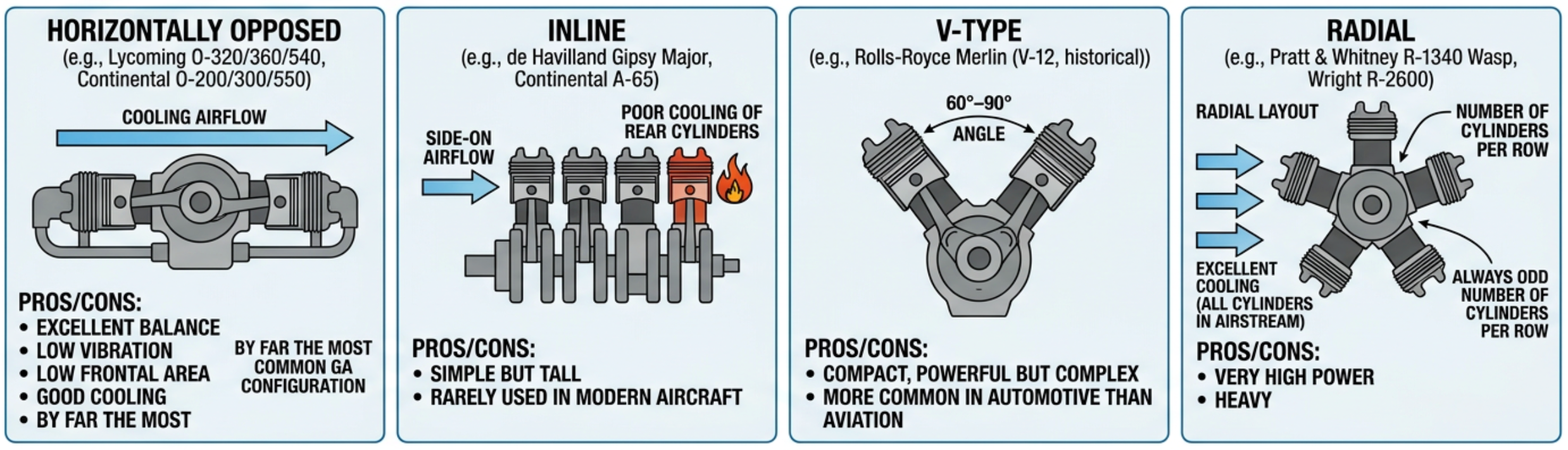
| Configuration | Characteristics | Examples |
|---|---|---|
| Horizontally Opposed | Cylinders in two banks, opposite each other. Excellent balance, low vibration, low frontal area, good cooling. By far the most common GA configuration. | Lycoming O-320/360/540, Continental O-200, O-300 and IO-550 |
| Inline | All cylinders in a single row. Simple but tall, poor cooling of rear cylinders. Rarely used in modern aircraft. | de Havilland Gipsy Major, Ranger L-440 |
| V-type | Two banks of cylinders at 60°–90° angle. Compact, powerful, but complex. More common in automotive than aviation. | Rolls-Royce Merlin (V-12, historical) |
| Radial | Cylinders arranged in a star pattern around the crankshaft. Excellent cooling (all cylinders in airstream), very high power, heavy. Always odd number of cylinders per row. | Pratt & Whitney R-1340 Wasp, Wright R-2600 |
The Horizontally Opposed, or Flat, Engine
The horizontally opposed layout is also called a flat engine, and the two names describe exactly the same machine — "flat four" and "horizontally opposed four-cylinder" are interchangeable. The cylinders lie on opposite sides of the crankshaft in the same horizontal plane, so the angle between the two banks is 180 degrees. That single geometric fact is where almost all of the layout's advantages come from.
- Balance. Cylinders in opposing pairs move outward and inward together, so the reciprocating inertia force of one is cancelled almost exactly by its opposite number. What remains is a small rocking couple, because, with each cylinder on its own crank throw, as these engines have, the two cylinders of a pair cannot occupy the same station along the crankshaft and are therefore slightly offset. This is why a flat engine runs smoothly with relatively little balancing mass on the crankshaft.
- Frontal area. The engine is wide but very shallow, so it fits inside a slim, low-drag cowling and leaves the pilot a view over the nose.
- Crankshaft length. Every cylinder has its own crank throw, so a six-cylinder flat engine has six of them, the same number a six-cylinder inline needs. The difference is how they are spaced along the shaft: the two throws serving a facing pair lie immediately next to one another and are set 180 degrees apart, so the six are grouped into three closely spaced pairs rather than strung out one behind another down the whole length of the crankshaft. The same six cylinders are therefore carried on a much shorter shaft. A short, stiff crankshaft resists torsional vibration far better than a long one.
- Cooling. Every cylinder projects into the airstream on its own, rather than sitting in the wake of the one in front, so with correctly fitted baffles each one can be given its own supply of cooling air.
Almost every certified light aircraft engine in current production is a flat four or a flat six; flat eights exist but are far less common. Construction is characteristic: the crankcase is split vertically on the centreline into two halves that clamp the main bearing shells between them, and long through-bolts pass right across the engine, retaining the main bearings and the cylinder base flanges at the same time. This is why cylinder removal on such an engine is not a self-contained job — slackening the wrong fasteners disturbs the main bearing clamp-up, and the torque sequence in the manual exists to protect it.
Inline and Inverted Inline
A single row of cylinders gives the simplest possible crankcase and leaves one whole side of every cylinder accessible, which is why the layout persisted so long in training and touring aircraft. Its weaknesses are the ones the table above names. The engine is tall, and cooling of the rear cylinders is poor because the air reaching them has already passed over — and been heated by — every cylinder ahead of them, so temperatures rise progressively down the row. A long crankshaft, with all its torsional consequences, is a further penalty of putting every cylinder in one line.
Both of the examples given in the table for the inline configuration are inverted designs, with the cylinders hanging below the crankshaft. Inverting the engine raises the propeller shaft relative to the bottom of the cowling, which gives better propeller ground clearance and a better forward view, and it puts the accessories and the crankcase where they are easy to reach from above.
Inverted engines and hydraulic locking. When an inverted engine is shut down, gravity works against it: oil that has drained down the cylinder walls, and any fuel that has seeped past a valve, collects in the combustion chambers and the cylinder heads, which are now the lowest point. Liquid does not compress. If enough accumulates and the engine is then turned under starter power, the piston can be stopped dead against it and a connecting rod bent or a cylinder head cracked. The same hazard exists on the lower cylinders of a radial engine and for the same reason. The engine maintenance manual states the procedure — typically involving removal of the lower spark plugs to drain the affected cylinders — and it must be followed before the engine is turned under power after any period of standing.
The V-Type
The V layout folds two banks of cylinders onto a single crankshaft. Compared with an inline of the same cylinder count, the engine is roughly half as long, its crankshaft is far shorter and stiffer, and its frontal area is only moderately greater. That combination is what made it the layout of choice for high-power military engines in the piston era, where the cylinder count needed to be high and the crankshaft still had to survive.
The bank angle matters mechanically as well as dimensionally: it determines how the firing impulses of the two banks interleave and how well the primary forces balance. The 60 to 90 degree range noted in the table is not arbitrary. The great V-12 aero engines were also liquid cooled, which is what allowed the banks to be brought so close together — there was no requirement to force cooling air between and around every cylinder. The price was a radiator, its ducting, its drag, its coolant and the vulnerability of the whole system to a single leak.
The Radial
A radial engine arranges its cylinders like the spokes of a wheel around a single crank throw, with all of them equally spaced and all of them directly exposed to the airstream. Its internal arrangement is unlike any other layout: one master connecting rod runs from its piston to the crankpin, and every other piston drives an articulated or link rod that is pinned to a flange on the big end of that master rod. A consequence worth remembering is that the link-rod pistons do not describe quite the same motion as the master-rod piston, so their effective strokes and compression ratios differ very slightly from cylinder to cylinder.
The requirement for an odd number of cylinders in each row follows directly from the four-stroke cycle. For even firing, the engine must fire alternate cylinders around the circle. Starting at cylinder 1 in a nine-cylinder row and taking every second cylinder gives 1, 3, 5, 7, 9, then 2, 4, 6, 8, and only then back to 1 — every cylinder visited exactly once in the 720 degrees of the cycle. Try the same thing with an even number of cylinders and taking every second one returns to the starting cylinder after covering only half of them, leaving the other half unfired. An odd count is therefore not a tradition but an arithmetic necessity.
Where more power is needed than one row can provide, rows are stacked: a twin-row radial of fourteen cylinders is two rows of seven, and one of eighteen cylinders is two rows of nine, with the rear row staggered so that its cylinders sit in the gaps between those of the front row. The two engines named in the table illustrate both arrangements — a nine-cylinder single-row engine and a fourteen-cylinder two-row engine. Multi-row engines cool the rear row far less easily than the front, which is why cooling gills, baffles and cylinder head temperature monitoring became so important on large radials.
The layout's virtues are cooling, a very short and rigid crankshaft, and an excellent power-to-weight ratio for its era. Its vices are the ones that ended its dominance in front-line use: a large frontal area and therefore high drag, considerable weight, and the oil consumption and hydraulic-locking behaviour that come from having cylinders below the crankshaft.
Rotary: Two Different Engines Sharing One Word
"Rotary" is used for two entirely different machines, and the examination will not tell you which one it means.
The historical rotary of the First World War — the Gnome and Le Rhone engines and their contemporaries — looks like a radial and is not one. Its crankshaft is bolted to the airframe and does not turn; instead the crankcase, the cylinders and the propeller all rotate around it as a single mass. That gave excellent cooling and a very large flywheel effect, but also enormous gyroscopic forces in a turn, total-loss lubrication with castor oil, and no practical means of throttling. The layout was obsolete by the 1920s.
The Wankel rotary is a modern engine with no pistons at all. A roughly triangular rotor with curved faces turns eccentrically inside a housing whose bore is an epitrochoid — a figure-of-eight-like shape rather than a circle. Each of the rotor's three faces forms a chamber with the housing wall, and as the rotor turns, each of those chambers is carried past the intake port, through compression, past the sparking plugs, through expansion and past the exhaust port. Every face therefore completes a full four-phase cycle in one revolution of the rotor, so the engine produces three power events per rotor revolution. The output shaft is geared to the rotor so that it turns three times for each single revolution of the rotor, which gives one power event per output shaft revolution from each rotor.
| Wankel rotary — advantages | Wankel rotary — disadvantages |
|---|---|
| Very high power-to-weight ratio for its displacement | Higher specific fuel consumption than an equivalent piston engine |
| Far fewer moving parts — no valves, camshaft, pushrods, connecting rods or reciprocating pistons | Apex seals at the rotor tips run against the housing at high speed and are the principal wear and reliability concern |
| Exceptionally smooth, because nothing reciprocates and the rotating masses are easily balanced | The long, thin combustion chamber has a poor surface-to-volume ratio, so it loses heat readily and burns incompletely |
| Compact for the power delivered, with ports instead of a valve train | Higher exhaust emissions, particularly unburnt hydrocarbon, and weaker torque at low speed |
Wankel engines have found a place in unmanned aircraft and in a small number of light aircraft installations, where compactness and smoothness are worth more than fuel burn. They are covered further in the study note dealing with alternative engine constructions.
Balance, Vibration and the Number of Cylinders
Configuration and firing order exist in the same section of the syllabus because they solve the same problem from two directions. The configuration decides what forces the moving parts generate and how they can be made to cancel; the firing order decides how the combustion impulses are distributed in time. Vibration is what is left over when neither has been arranged well.
Three distinct sources of vibration act on a piston engine, and they behave differently:
- Rotating out-of-balance. The crank throws, the big ends and part of the connecting rod mass all whirl about the crankshaft axis. This is the easiest source to deal with because it can be balanced completely by fitting counterweights of the right mass in the right angular positions.
- Reciprocating inertia. The piston, gudgeon pin and the upper part of the connecting rod stop and reverse twice per revolution, and the force required to do that acts along the cylinder axis. It cannot be cancelled by a rotating counterweight alone; it has to be cancelled by another piston moving the opposite way, which is precisely what the opposed configuration provides.
- Torque reaction and firing impulses. Each power stroke delivers a sudden twist to the crankshaft, and the crankshaft delivers an equal and opposite reaction to the crankcase and thus to the engine mounts. This is a torsional excitation, and it is why engines are carried on flexible mounts rather than bolted rigidly to the airframe.
The cylinder count acts on the second and third of these at once. It acts on the third because it sets how closely one firing impulse follows the next, and the closer they come the less the crankshaft speed can fall away between them. It acts on the second because more cylinders give the designer more freedom to oppose one residual couple with another: a flat six can be laid out so that its three opposing pairs cancel each other and is inherently balanced, whereas a flat four is left with a rocking couple it cannot cancel from within itself. That combination of smoother delivery and better balance, rather than extra power alone, is a large part of why the flat six became the standard at the higher end of the light aircraft market.
Torsional vibration deserves separate attention because it is the source that can destroy a crankshaft. The crankshaft, the propeller and everything geared to them form an elastic system with natural frequencies of its own. If the firing impulses arrive at a frequency close to one of those natural frequencies, the twisting oscillation builds up instead of dying away, and the stresses can exceed anything the steady loads would produce. The consequences are visible in the way engines are certificated and operated:
- Some installations carry a restricted rpm range that must be transited rather than operated in continuously. It is a placarded limitation and it exists because of a torsional resonance, not because the engine is generally unhappy at that speed.
- Larger and higher-powered engines carry dynamic counterweights on the crankshaft — pendulum masses hung on the crank webs, free to swing on oversized pins so that they oscillate out of phase with the firing impulses and absorb the torsional energy. They are tuned to a particular order of vibration, so their pins and bushings are matched components that must not be interchanged.
- The propeller is part of the system. Changing to a propeller of different mass or polar moment of inertia changes the natural frequency of the whole assembly, which is why propeller and engine combinations are approved together and why an apparently harmless substitution requires approved data.
A rough-running engine is a symptom, not a diagnosis. Uneven running can come from combustion — a dead cylinder, a fouled plug, an induction leak on one cylinder, a valve not sealing — or from the mechanical sources above, such as a failed engine mount, an out-of-balance propeller or a damaged dynamic counterweight bushing. The two families feel different and are found by different means: the first shows up in the cylinder-by-cylinder indications and the magneto check, the second is largely independent of power setting and mixture and often changes character with rpm. Deciding which family the symptom belongs to is the first step, and it is the step most often skipped.
Cylinder Numbering
A firing order is a list of cylinder numbers, so it means nothing without the numbering convention it was written for, and conventions are not universal.
On a radial engine the convention is settled and worth memorising: number 1 is the cylinder at the top, and the remaining cylinders are numbered in order around the circle, counted clockwise when the engine is viewed from the rear. On a multi-row radial the front row and the rear row are numbered as part of one continuous sequence rather than separately.
On horizontally opposed engines the position of cylinder number 1 is a manufacturer's choice, and the two principal manufacturers of these engines do not start from the same end of the crankcase. An engineer who takes a firing order from one manufacturer's data and applies it to another manufacturer's cylinder numbering will connect the ignition leads to the wrong cylinders while believing the sequence to be correct. Always take the numbering diagram and the firing order from the same document, and that document must be the manual for the engine actually installed.
Firing Order
The firing order is the sequence in which cylinders fire. It is designed to:
- Distribute thermal stress — avoid adjacent cylinders firing consecutively
- Minimise vibration — balance the crankshaft loading
- Ensure smooth power delivery — evenly space power strokes
Typical firing orders:
- 4-cylinder opposed: 1-3-2-4 or 1-4-2-3
- 6-cylinder opposed: 1-4-5-2-3-6
- Radial (5-cylinder): 1-3-5-2-4 (every other cylinder around the circle)
In a 4-stroke engine, power strokes are spaced every 720° ÷ N of crankshaft rotation (where N = number of cylinders). For a 4-cylinder engine: 720° ÷ 4 = 180° between power strokes.
How a Firing Order Is Constructed
A firing order is not chosen for elegance. It is the solution to several constraints that have to be reconciled with one another, and understanding them makes the published sequences memorable rather than arbitrary.
- Even spacing of the power impulses. The cycle must be divided equally between the cylinders so that the crankshaft receives a push at regular intervals rather than in bursts. This is what makes the torque delivery smooth.
- Alternation between banks, or around the circle. Consecutive firings are placed on opposite sides of the engine wherever possible, so that the loads on the crankshaft and crankcase swap from side to side instead of hammering the same region repeatedly.
- Separation of neighbours in time. Two cylinders that are physically adjacent should not fire one after the other wherever the crankshaft layout allows it. If they did, one region of the crankcase and cylinder-head casting would take two heat pulses in quick succession, and on a shared induction manifold the second cylinder would be trying to draw its charge through a passage the first had just emptied — the effect called induction robbing, which leaves that cylinder running lean. On a four-cylinder opposed engine that separation cannot be achieved in full. The four cylinders are carried as two facing pairs, and the two cylinders of a pair reach top dead centre together, so they fire a full revolution apart rather than one after the other; with a power stroke every 180 degrees the sequence must therefore alternate from one pair to the other. Each pair has one cylinder on each side of the engine, so two of the four transitions are bound to fall between the two cylinders on the same side, whichever of the orders listed above for that engine is used, and no reordering can avoid it.
- Crankshaft balance. The order has to work with the crank throw arrangement, not against it, so that the firing impulses do not reinforce the out-of-balance couples.
The even-spacing constraint is the one that can be calculated. In a four-stroke engine the cycle occupies 720 degrees of crankshaft rotation and each cylinder contributes one power stroke to it, so the interval between firings is 720 degrees divided by the number of cylinders. A two-stroke engine completes its cycle in 360 degrees, so the same reasoning gives an interval of 360 divided by the number of cylinders — another reminder that a firing interval quoted without the cycle it belongs to is meaningless.
Firing intervals for common engines (four-stroke):
- Six-cylinder: 720 ÷ 6 = 120 degrees between firings
- Five-cylinder radial: 720 ÷ 5 = 144 degrees
- Nine-cylinder radial: 720 ÷ 9 = 80 degrees
- Fourteen-cylinder twin-row radial: 720 ÷ 14 = about 51.4 degrees
There is a threshold worth spotting in those numbers. A power stroke occupies 180 degrees of crankshaft rotation, so at a firing interval of 180 degrees a four-cylinder four-stroke engine has exactly one cylinder producing torque at any instant, with no overlap at all. At 120 degrees a six-cylinder engine always has one and a half; at about 51 degrees a fourteen-cylinder radial has three and a half. Fewer than four cylinders and the interval exceeds 180 degrees, leaving gaps in which no cylinder is delivering anything and the rotating inertia has to carry the engine through unaided.
Following a six-cylinder opposed sequence through the cycle. Taking the order 1-4-5-2-3-6 listed above and applying the 120 degree interval, the cylinders fire at:
- 0 degrees — cylinder 1
- 120 degrees — cylinder 4
- 240 degrees — cylinder 5
- 360 degrees — cylinder 2
- 480 degrees — cylinder 3
- 600 degrees — cylinder 6
- 720 degrees — cylinder 1 again, and the cycle repeats
Six firings, evenly spaced, with every cylinder used exactly once in the two revolutions. Any valid firing order must pass this test; a sequence that repeats a cylinder or leaves one out inside 720 degrees is simply wrong.
Firing Order in the Hangar
Firing order is one of the few pieces of pure theory in this subject that an engineer uses directly, with a spanner in hand.
- Ignition harness connection. The distributor block of a magneto has its terminals numbered in the order in which the magneto distributes the sparks, not by cylinder number. The leads therefore run from terminal 1, 2, 3 and so on to the cylinders taken in firing order, not in numerical order. Connecting the harness "logically" — terminal 1 to cylinder 1, terminal 2 to cylinder 2 — produces an engine that may still start and run, roughly and with a distinctive misfire pattern, which makes the fault harder to recognise than an outright failure would be.
- Magneto timing. The engine is timed with a nominated reference cylinder, conventionally number 1, brought to the specified number of degrees before TDC on its compression stroke. The qualification matters: the crankshaft passes TDC twice in the cycle, and only one of those is the firing position for that cylinder. Confirming that both valves are closed, or feeling compression at the plug hole, is how the correct one is identified.
- Compression checks. A differential compression check requires each cylinder in turn to be brought to TDC on its compression stroke. Working through the cylinders in firing order means the propeller is turned by only the firing interval between each test rather than being rotated back and forth, which is quicker and safer.
- Fault interpretation. When an engine runs rough, knowing which cylinders fire consecutively and which share an induction passage turns a vague symptom into a short list of suspects.
Never infer a firing order from the cylinder count. Two engines with the same number of cylinders in the same configuration, from different manufacturers, may use different firing orders and different cylinder numbering. Getting either of them from the wrong document, or from memory, will cross-connect the ignition leads. The firing order and the cylinder numbering diagram must both come from the maintenance manual for the specific engine model and dash number in front of you, and the harness should be checked lead by lead against that diagram before the cowling goes back on.
Printing is not available
Please view study notes online at part66online.com